3D-printing-oriented design
PIAP supports CAD designers in geometry optimization of designed prototypes (in particular internal geometries) for required strength properties, weight and cost-effective use of materials for 3D printing.
Modern machines for additive manufacturing include special software for creating CAD model of a designed prototype for the additive process. The software, apart from dividing geometry into layers, generating model supporting structures and controlling the additive process parameters (e.g. temperature in the machine working chamber) allows to generate internal geometries (e.g. internal filling).
This function has its pros and cons. Its pros include an ability to quickly generate the selected internal geometries – lattice, ribbing, honeycomb etc. On the other hand, the software has limited capabilities to model and change parameters of internal geometries, by allowing programming filling parallel to the model table plane only. Generating internal geometry by the software for additive processes is not related with the modifications of the original CAD model of the prototype (no backward compatibility). In additive technologies, CAD design requires two somehow independent stages in two different software (i.e. CAD environment and machine manufacturer software) which is far from optimal solution.
PIAP has started research on the methods of modelling the internal geometry for prototypes created using incremental manufacturing using CAD software only. The method allows to model any internal geometries, which can be manufactured using incremental methods.
Rys. 1. Model CAD prostopadłościanu (niebieski) wraz z przykładowym narzędziem do tworzenia własnej geometrii wewnętrznej
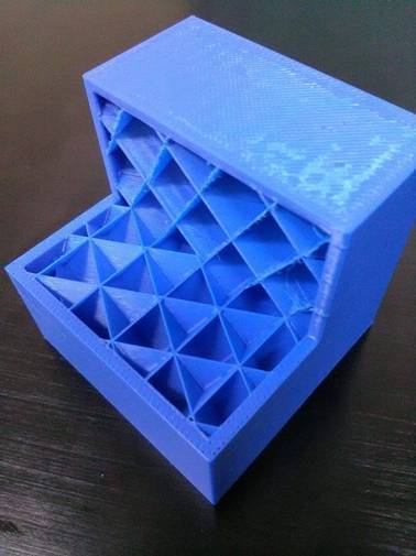
Rys. 2. Prostopadłościan z materiału ABS-M30 z zaprojektowaną w systemie CAD geometrią wewnętrzną, wytworzony na maszynie FORTUS 400 mc. Jest to pierwszy model, którego geometria wewnętrzna została w całości zaprojektowana w systemie CAD i nie jest zorientowana równolegle do płaszczyzny stołu maszyny
To, co będzie stanowiło o jej unikatowości, to możliwość wykorzystania zaprojektowanej geometrii bezpośrednio do obliczeń metodą MES w celu szacowania wytrzymałości opracowanych prototypów z zaprogramowaną geometrią wewnętrzną i ich optymalizację. Dzięki temu w wyniku jednego procesu projektowania CAD możliwe jest wykonanie dwóch niezależnych operacji jednocześnie – obliczeń komputerowych i bezpośredniego wytwarzania metodą przyrostową części, których geometria wewnętrzna będzie dopasowana do warunków brzegowych (obciążeń, zamocowań itp.).
Aktualnie prace są realizowane na prostych, reprezentatywnych geometriach – prostopadłościan, kula, walec. W kolejnym etapie będą badane bardziej skomplikowane geometrie – wybrane części robotów mobilnych.


